|
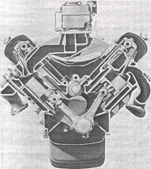
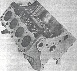
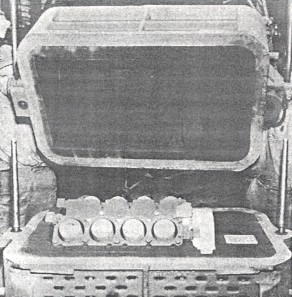
The New American Motors V-8 Engine John F. Adamson, Carl E. Burke and David B. Potter American Motors Corp. This paper was presented at the SAE National Passenger-Car, Body and Materials Meeting, Detroit, Michigan, March 7, 1956. Enough has been said about V-8 engines, to preclude any discussion in this paper about the inherent advantages and disadvantages of this type of design. Rather, we shall attempt to set forth, not only the end results of our design and development efforts, but some of the more interesting problems involved in bringing the new American Motors V-8 engine to the automotive market. Many of the desirable design features pioneered by Nash and Hudson on our 6-cylinder power plants have beer incorporated into this new V-8. We have drawn from a wealth of experience that includes 39 years of overhead-valve production at Nash, and the well-known ability of Hudson to develop high-performance engines. These features have been retained, in addition to ideas resulting from a very careful and thorough analysis of the newest industry-wide practices and methods. The above, together with a great deal of forward thinking, has produced an engine that will power a new series of cars; the Nash Statesman V-8, and the Hudson Hornet Special V-8 for 1956. Basic Design and Flexibility In addition to producing an engine with high performance characteristics, we had basically four other prime objectives in mind when we started to Put together the production version of our various experimental projects, engineering studies, and previously approved designs. We have through the years built a reputation for economical and dependable engines, and it was not our intention to sacrifice this or any other past objective in the new design. In short, we also wanted: 1. An engine that would be flexible enough to be readily adaptable to future displacement requirements, compression-ratio changes, and any of the other forward reaching, revisions of the automotive industry today. 2. An engine that could be easily installed in our present and future bodies, and would also lend itself to our methods of production assembly. At the same time, we wanted an installed engine that would be readily accessible for service. 3. An engine that incorporated the latest and most economical methods of manufacturing processes. 4. An engine with the lowest possible weight, without sacrificing durability. The new 3-1/2 in. bore by 3-1/4 in. stroke, 250-cu in. V-8 (Figs. 1 and 2) was designed to accommodate greater displacement than is actually being produced this year. As examples, the valve sizes were determined by future breathing requirements, as were both the intake and exhaust port systems. The crankshaft forging was designed to give 100% balance for much heavier reciprocating and rotating weights than now carried and the water and oil pumps have a greater capacity than presently required. The cylinder center distance of 4-3/4 in. is considerably larger than that required for a 3-1/2 in. bore, and allows for future increases without sacrificing coolant flow around the cylinder walls. Main bearing caps, bolts and connecting rods have likewise been designed for a greater load-carrying capacity.
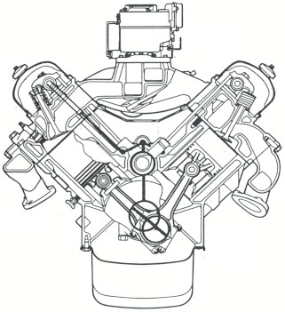
Fig. 1- Transverse cross-section of American Motors V-8 engine
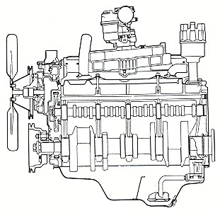
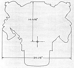
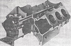
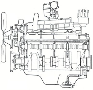
Fig. 2 - Longitudinal cross-section The above features, together with other factors will allow for increased engine displacement without extensive tooling changes. The crankshaft balancing equipment would be revised only with regard to "bob-weights," while no changes are needed on the block other than the pattern and machining revisions for bore size. As mentioned previously, the valves have been actually designed for a greater displacement, and consequently, the only chance required in the cylinder head for shifting to a bigger engine would be the revising of the cast combustion chamber. Engine Size With regard to engine size, we set out to produce an engine that could be easily installed in not only our present line of cars, but also those projected for the future. From the styling standpoint, it had to be a low engine, and from the assembly installation standpoint, it was desirable to minimize width and length. These objectives were obtained by making the term compact" the byword of the entire project. A short stroke of 3-1/4 in. was chosen to reduce height and width, and the crankshaft counterweights are contoured to further shorten the distance from the crankshaft centerline to the top of the block. Exhaust manifolds are carried below the port openings in the head, and the intake port facings are held parallel to the cross-sectional centerline of the banks to further reduce the height of the carburetor flange. As shown in Fig. 3, the above items allowed us to design an engine that has a width of 24-1/8 in. across the exhaust manifolds, and a height from the crankshaft centerline to the carburetor flange of 14-15/16 in. The overall length from the back face of the engine to the center of the fan pulley is 27-23/32 in. It must also be borne in mind that these dimensions will remain unchanged for an engine of greater displacement than the present 250 cu. in.
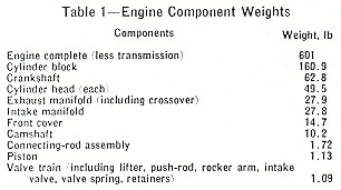
Fig. 3 - Engine outlline Although servicing an installed engine is one of the problems of V-8 design, a number of features were adopted to ease this problem. Spark plugs are located well above the exhaust manifolds, and are in a nearly vertical position for easier removal and installation. Service consideration was also given to the generator, as it is located at the upper right-hand side of the engine and outside of the tappet cover for easier accessibility. In addition, the distributor has a tang length, for mating with the oil pump shaft that allows this engagement to be made prior to engagement of the distributor gear with the camshaft drive gear. Manufacturing Exceptionally close liaison was maintained with our manufacturing personnel during the design and development stages of the engine. As a result, many economies in fabricating and tooling processes were built into the original design and have since been carried through into production. Tooling facilities for the V-8 are completely new, and are based on what we call "segmented automation." In this type of manufacturing, each basic section of tooling, although completely automatic, is not fully integrated with other sections. For our purposes, this type of tooling means increased flexibility as each portion of the line can be utilized independently of other operations. Of particular interest is the cylinder-block boring equipment, which has been designed to finish simultaneously blocks of two different bore dimensions. It contains two sets of roughing, finishing, and chamfering tools, and blocks of either bore size can enter the equipment in any mixed sequence. Each station is set to tool one size bore, and when a block enters that station, a probe automatically determines whether or not to cycle the cutting heads. Engine Weight The many features incorporated to keep engine height and length to an absolute minimum have aided tremendously in reducing engine weight. In addition, every possible design detail has been very carefully investigated for possible further weight reduction. Loading and stressing of all parts was painstakingly calculated to make sure that we were not guilty of over-designing. Regarding the loading and stressing of parts, all components, where applicable, were considered for use with the larger displacement versions of this engine. Consequently, even though the weight of the present production engines compares very favorably with competitive power-plants, the advantages of our weight-saving program will be much more apparent in future versions of this engine. Actual weights of the various major component parts are listed in Table 1.
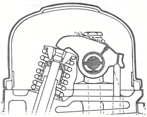
Table 1 - Engine component weights Cylinder Block As any engine is basically built in and around the cylinder block (Fig. 4), this component is the biggest factor in regard to power-plant size, weight, and flexibility. Even engine harshness and durability of the drive-train parts depend on the rigidity and design of the block. In the American Motors design, every effort has been made to provide a satisfactory base upon which to build the engine.
Fig. 4 - Cylinder block The crankcase flange has been carried 2-3/4 in. below the crankshaft centerline to provide inherent stiffness and a good oil pan sealing flange. The flywheel housing mounting surface provides a wide and deep base for drive-train mounting, and the 30 cylinder-head bolts give a pattern that carries the gas pressure load evenly into the water jacket walls rather than into the cylinder bores. This arrangement reduces distortion and consequent abnormal wear of the bores, pistons, and piston rings. (See Fig. 5.)
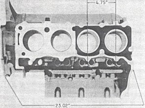
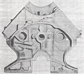
Fig. 5 - Cutaway of cylinder block showing design for rigidity Due to the fact that the block comprises the greatest weight of any component in the engine, it provides a lucrative field in which to effect weight reduction. We have taken advantage of this fact wherever our tests and previous experience has shown it to be possible. Working from the bore-to-bore distance of 4-3/4 in. established by future displacement needs, the overall length of the block has been held to 23.02 in. by careful consideration of coolant and loading needs, as shown in Fig. 6. Windows have been cast in the main bearing webs where strength requirements showed it possible, and as can be seen in Fig. 7, pockets have been cast on either side of the rear flange for further weight reduction. The right pocket nestles the starter close to the crankcase and allows the starter to be fastened to lightweight die-cast aluminum flywheel housing. It is obvious that we cancel several machining operations for a starter pad normally found on the block, and in addition omit a considerable amount of cast iron. We estimate that a saving of approximately 15 lb. of metal has been realized on the rear of the block alone.
Fig. 6 - Cyliner block dimensions
Fig. 7 - Cylinder block rear face You will notice in Fig. 8 that manufacturing savings have been obtained by eliminating hard sand cores wherever possible. Green sand has been provided for the front, side, top, and tappet chamber sections, and hard sand cores for only the crankcase, bores, water jackets, and rear face. All cores are machine set to minimize breakage.
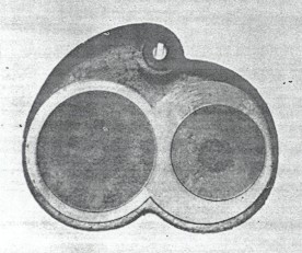
Fig. 8 - Cylinder-block core assembly Machining operations where also taken into account during the design stages of the engine, which resulted in the complete lack of any machining setup carried out for one drilling or surfacing operation only. Combustion Chamber We have chosen for this engine, a type of chamber that gives us what we consider the more important of the various characteristics obtainable for a good, efficient combustion chamber. The design used can best be described as a kidney-shaped, wedge-type, cast chamber. Excellent results have been obtained on our recent 6-cyl engines with this type of configuration, and it inherently contains a number of the factors we desired. Being cast, it requires a minimum of machining, and consequently, volume can be placed just where we want it. The kidney shape gives a swirling action to the intake gas for better turbulence, and spark-voltage requirements are quite low. As shown in Fig. 9, there is no shrouding of the valves and, therefore, a high volumetric efficiency is obtainable. Combustion characteristics are such that chamber shape controls the rate of pressure rise to minimize engine harshness. A compression ratio of 8.0:1 has been chosen to allow this engine to burn regular fuel and, therefore, further effect economy of operation.
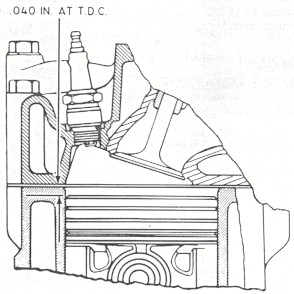
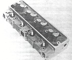
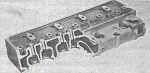
Fig. 9 - Cast combustion chamber As can be seen from Fig. 10, the spark plugs are effectively cooled by the considerable volume of water surrounding them. These plugs are located in the chamber in such a manner as to minimize the "drowning effects" of unvaporized fuel during cold starts. Fig. 11 shows the location of the plugs in the head.
Fig. 10 - Combustion chamber
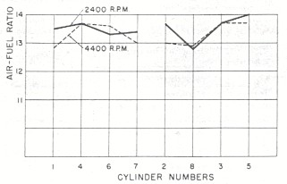
Fig. 11 - Cylinder head showing location of spark plugs Ports and Manifolds The purpose of induction and exhaust systems is efficiently to feed and scavenge an engine under all driving conditions. The intake manifold must be much more than just an inlet to a high-speed air pump, and the exhaust system must be scientifically balanced for the load it carries. Many major and minor chances were made in the intake manifold for this engine before the production version was agreed upon. Numerous cold and hot starting tests, plus runs under all operating conditions, were made in order to provide a manifold that would give the average driver a "satisfactory feeling" engine. Fig. 12 plots the air-fuel distribution by this manifold to the various cylinders under the conditions shown.
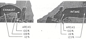
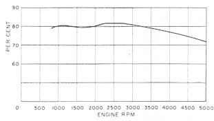
Fig. 12 - Fuel/air ratios Fig. 13 shows the basic configuration of the intake and exhaust port designs. Starting with the intake port opening in the head, it can be seen that a smoothly balanced transition is obtained in relation to the valve opening. The slight restriction of flow and consequent increase in gas velocity tends to develop a ram effect at the valve, with subsequent increase in engine torque. Valve size is such that the theoretical gas velocity through the valve is lower than that of any automotive engine on the market today. The full-throttle variation of volumetric efficiency with speed is shown in Fig. 14.
Fig. 13 - Intake and exhaust port areas
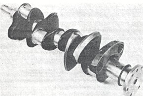
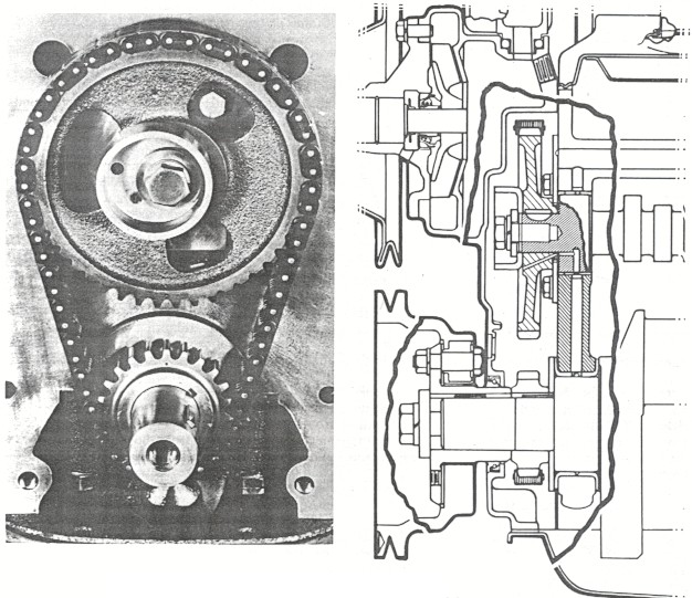
Fig. 14 - Volumetric efficiency at full throttle It can be seen that exhaust ports have also been designed to give balanced areas. Port size is increased as gases move away from the valve to give efficient scavenging and minimize backpressure. Exhaust manifolds are ample in area and provide for a smooth, continuous flow of exhaust gases. Crankshaft The crankshaft is a steel forging with five main bearings and six counterweights, as shown in Fig. 15. Shaft length from the flywheel flange to the front edge of the sprocket shaft is 27.2 in., and a journal overlap of 3/4 in. provides increased stiffness.
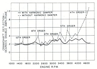
Fig. 15 - Crankshaft As previously mentioned, all counterweights are cam-turned to realize fully every possible reduction in engine height. In addition, the checks are chamfered to allow the contoured skirts of the pistons to nest closer to their respective crankpins when at bottom dead center. This in turn, shortens connecting-rod length, and further reduces engine height. Depressions are cast in the bottom jacket walls of the cylinder block to allow for clearance with the counterweights. Fig. 16 shows the torsional vibration characteristics of this engine both with and without a harmonic damper. As can be seen, the rubber and friction type of damper used reduces all orders of frequency within the engine speed range to negligible amplitudes.
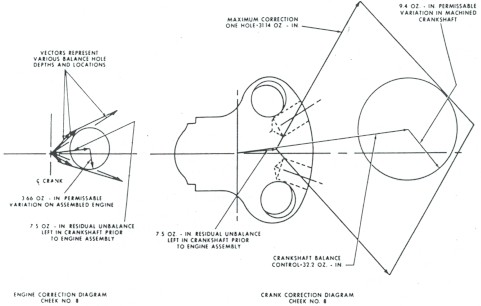
Fig. 16 - Crankshaft torsional vibrations A particularly interesting problem in the design of the engine centered around the balancing of the crankshaft. The crank forging itself had to contain enough inherent balance control to take care of future displacement requirements. However, at the same time it could not have more overbalance when used with the engine under discussion, than our balancing equipment could remove. Reciprocating and rotating weights, or what are more commonly referred to as "bob-weights," were carefully calculated for all contemplated displacements prior to the final approval of the crankshaft design. This design was made in such a manner that no tooling changes would be needed prior to the initial balancing of the crankshaft itself. For engines with displacements of over 250 cu in., a very minor resetting of the balancing equipment is all that is needed. Fig. 17 shows the vectors involved in the balancing operations on the crankshaft, with the right-hand portion representing the initial balancing on the machined crank. This operation consists of drilling two 1-5/8 in. diameter holes into the faces of both No. 1 and No. 8 cheeks, and reduces the overbalance of the crankshaft to a value of 7.5 oz-in. in a predetermined plane. This figure shows the maximum correction factor of 3 1.1 oz-in. obtainable with each drilled hole, plotted as a vector in both magnitude and direction. The ensuing parallelogram contains the area in which balancing correction can be made to the 7.5 oz-in. value.
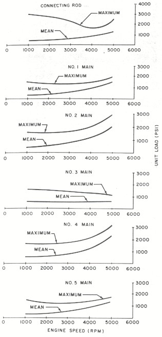
Fig. 17 - Crankshaft balancing The designed balance of the machined crankshaft, including "bob-weight" equivalents, is represented by the vector shown. From this vector, there is a permissible variation of 9.4 oz-in. due to possible forging and machining variations. This vector must fall within the correction capacity of the two 1-5/8-in. diameter balancing holes. The depth of the drilled holes, will, of course, vary with the correction needed. As engine displacement is increased, "bob-weights" obviously become heavier, and the balance control of the crankshaft is reduced below 32.2 oz-in. However, as long as the permissible variation circle struck from the end of the crankshaft balance-control vector falls within the parallelogram formed by available correction, the same finished crankshaft can be used. The crankshaft is then assembled in the engine with connecting rods, pistons, piston pins, piston rings, flywheel, and crankshaft pulley attached. This assembly is then corrected for the 7.5 oz-in. left by the initial balancing, plus variations due to weight and balance tolerances of the attaching parts. The correcting is done by drilling two 15/16 in. diameter holes radially into the periphery of the No. 1 and No. 8 cheeks, with the location and depth of the holes varying with the amount of correction needed. The left portion of Fig. 17 (above) plots the vectors representing the various corrections obtainable due to location and depth of drilling, and a 3.66-oz-in. circle to cover the permissible component variations. This final operation balances the engine assembly to within a maximum tolerance of plus or minus 1/2 oz-in. Bearings Further economy and assembly simplicity has been designed into the engine through the use of bearing interchangeability. All five main bearing diameters are 2.499 in., and, with the exception of the front, which is flanged to take crankshaft thrust, are interchangeable. Effective bearing area for the intermediate and rear mains is 2.20 sq. in., while the front is 2.08 sq. in. Full 360-deg grooving is used to make the bearing halves similar, and also to insure adequate flow of oil to the connecting rod at the time of registration for cylinder-wall lubrication. Connecting-rod-bearing halves are also similar throughout. Bearing diameter is 2.249 in., and effective area is 1.935 sq. in. All bearings are micro-babbitt with steel backs. Mean and maximum loads carried are plotted for the engine speed range in Fig. 18.
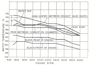
Fig. 18 - Bearing loads Cooling Engine durability is dependent in many ways on an efficient cooling system. Fig. 19 is a cutaway section through the valve centers in the head, and shows the results of the attention given to getting water around the valve seats. With this penetration of coolant, we obtain longer life and more trouble-free operation of the valves. Complete jacketing of the cylinders provides cooling for the entire length and circumference of the bores. Water flow has been designed to give complete coverage of the various portions of the engine, and as shown in Fig. 20, temperature variations of the coolant have been kept to a minimum.
Fig. 19 - Cylinder-head water passages
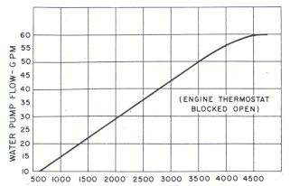
Fig. 20 - Coolant temperature variations A single, high-capacity pump provides the flow plotted in Fig. 21. This pump contains a 4-in. diameter plastic impeller, and is centrally mounted at the front of the engine. A drilled bypass is provided in the water manifold for coolant circulation during cold starts, and prior to the opening of the thermostat.
Fig. 21 - Water pump capacity The attention paid to the various cooling problems involved has resulted in relatively low heat-rejection characteristics. This, in turn, means high thermal efficiency and reduced required radiator capacity. Lubrication The basic flow of oil for the engine is shown in Figs. 22 and 23. It can be seen that the lubricant is picked up by the fixed-screen inlet and drawn into the pump. This pump, shown in Fig. 24, contains sintered iron gears and is an integral part of the rear main bearing cap. This type of design gives us a pump located well up towards the crankshaft centerline, and allows placing the oil pan sump in a variety of fore-and-aft locations. This, in turn, gives a great amount of flexibility with regard to the location of the steering linkage. The pump is driven through a tongue and groove connection with the distributor shaft, and is provided with an oil pressure relief valve.
Fig. 22 - Lubrication system
Fig. 23 - Lubrication system
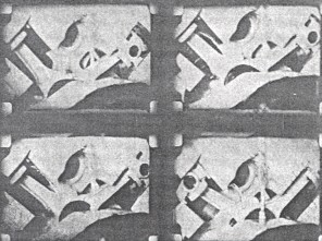
Fig. 24 - Oil pump From the pump, the oil is forced through the filter and into the main oil gallery. Flow is then down to the 7/64 X 5/16-in. annular grooves machined in the camshaft bearing webs, and thence to the main bearings. Except for oil fed to the camshaft bushings, it can be seen that the main bearings are fed prior to any oil being bled off to another location. This assures that the bearings farthest from the pump receive adequate lubrication. It might be interesting to note Fig. 25, which shows the intermittent lubrication of the chrome-plated fuel pump eccentric. This timed squirting of the eccentric is accomplished when the holes drilled in the front camshaft journal register with the camshaft bushing oil hole. Lubricant under pressure is then forced through a 3/32-in. diameter hole in the camshaft sprocket, and onto the pump eccentric. Aside from this same spray lubricating the timing chain, oil is picked up by the cast-in dam on the front cover and directed to the crankshaft sprocket.
Fig. 25 - Fuel pump eccentric and timing chain lubrication Fig. 26 contains actual photographs taken from a series of high-speed motion pictures showing cylinder-wall lubrication at 0° F, 40 psi, and 700 rpm. From these movies of various experimental designs, we were able to get a squirt pattern of the correct timing and intensity to provide adequate cylinder-wall and piston-pin lubrication.
Fig. 26 - Cylinder-wall lubrication The hydraulic lifters are fed through longitudinal galleries that intersect the lifter bores. These galleries are fed from the main gallery through grooves cast in the cast-iron camshaft thrust plate. Due to the fact that no lifter pump-up problems have been encountered in this engine, no attempt has been made to meter appreciably the flow of oil to the lifter galleries. The hollow rocker-arm shafts in each bank receive their oil supply from the lifter galleries, through short drilled holes in the cylinder head and rocker arm support bolts. These bolts are set in oversize drilled holes and the oil is carried around the bolt to the rocker shafts. This movement of oil is at the rear of the engine to provide continuous flow through the lifter galleries and thus to prevent the formation of sludge traps. An interesting approach to the matter of valve-stem lubrication during cold starts can be seen in Fig. 27. You will note that the rocker arms have a milled flat, which intersects the oil feed hole. We have found that this flat tends to break the surface tension of the cold oil oozing from the feed hole, and causes it to flow freely to the valve end of the arm. Tests have shown that the time required to get oil to the valve stem during cold starts, has been cut over 75% from our previous design. This milled flat also causes hot oil to spill over the sides of the arm and not to run down and overlubricate the valve stems. Oil-resistant rubber deflectors are fitted to the valve stems to prevent excessive oil being fed to the valve guides. These deflectors move with the valve stem, and allow oil mist to lubricate the stem and guide- when the valve is in the closed position.
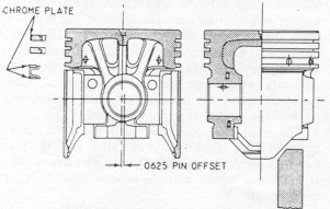
Fig. 27 - Rocker-arm lubrication Distributor lubrication is supplied through a drilled hole in the distributor body, which registers with the right-hand lifter gallery. Oil is fed through the distributor body into the distributor bushing, and carried to the gears by means of internal grooving in the bushing. Piston and Rings Following our previous practice, the new V-8 uses aluminum-alloy, steel-insert, autothermic pistons. These pistons have slippered skirts, are tin-plated, and have the piston-pin boss holes bearingized after plating. The latter assures an accurate bearing area for the pin, and helps prevent scuffing. As can be seen in Fig. 28, these pistons are of the double-slot design, and have three vertical ribs joining the head and pin bosses. These ribs support the bosses and tend to reduce deflections during the periods of high pin loading. The slipper-type skirt is shaped to match closely with the contoured counter- weights of the crankshaft when the piston is at bottom dead center. This serves further to reduce the required height of the cylinder block.
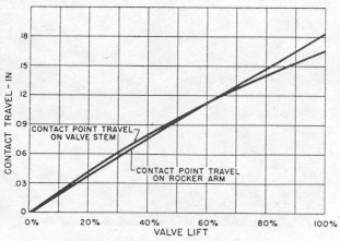
Fig. 28 - Pistons and rings The piston carries a head thickness of 0.25 in. to allow for its use with compression ratios well above the current 8.0:1. A 0.0625-in. offset of the piston pin toward the major thrust face gives exceptional freedom from "piston slap." Piston finished weight is 511 g and the balancing lugs allow for 31 g of weight control. As also shown in Fig. 28 (above), three rings are used. The compression rings are 5/64-in. wide alloy iron, with the top ring having a 0.004-0.007 in. thick, lapped chrome plating. The oil control ring is of the three-piece design made up of two rails and a spring steel spacer. The rails carry buffed 0.0025-in. minimum chrome plating on their reacting faces. Valve Train The present design is a continued development of quiet, durable, and trouble-free valve trains, and is made up of compact, light, and well-proved components. The camshaft is an alloy iron with five bearings, and is chain driven. All lobes carry a 15 maximum micro-in. finish, and the cams are ground with a 0.001-0.002-taper per in. The latter, together with spherical lifter faces and offset centerlines, insures positive lifter rotation. To obtain further quiet operation and peak performance, hydraulic lifters are used. Lifter bodies are hardenable iron, with a face hardness of 54 RC min, and are lubrited for improved break-in. Push-rod sockets are case-hardened steel, and a lifter internal operating range of 0.100 in. is available. The diameter of the lifter is 0.904 in., which gives an effective diameter of 0.900 in. when the centerline offset, spherical face, and tapered cam lobes are considered. This value is well above the 0.800 in. diameter required to keep the edge of the tappet face from digging into the cam lobe. The 0.800-in. diameter was computed from the cam-lift velocity, and as is apparent, there is ample space to utilize cam contours with more severe lift velocities. Critical pump-up speed for these tappets has been found to be well over 5000-rpm engine speed. The solid push rods are 1/4-in. diameter, and are made of SAE 1060 cold-drawn steel with the spherical ends hardened to RC 50 min. The overall length is 8.87 in., which assures a very rigid valve-train component. Rocker arms are cast pearlitic, malleable iron, and are extremely short to reduce valve-train deflection further. The arms are lubrited after finishing to help reduce scuffing of the rocker shaft. Rocker-arm geometry has been set up to give a minimum amount of slippage between the arm and the valve-stem tip during the periods of high loading. This high loading period occurs at the point of greatest lift acceleration, which on our cam occurs just prior to 20% of the lift. Fig. 29 shows the movement of the contact points along the rocker arm and the valve, with the vertical distance between these curves representing slippage.
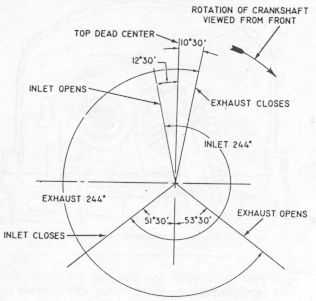
Fig. 29 - Rocker-arm geometry The intake valves, which are made of Silchrome No. 1 steel, have 1.787-in. diameter heads and 30-deg seat angles. The exhaust valves are of the two-piece construction with the head and upper stem made of SAE 2112N steel. Exhaust-valve head diameter is 1.406 in., and both valves operate with a moderate 0.375-in. lift. Because of the compactness and lightness of the valve train, spring forces can be kept relatively low. This, in turn, reduces lifter face stress, and eases lifter and camshaft wear problems. Valve Timing and Electrical System Due to the relatively large valves used with the present displacement, valve timing can be kept to conservative values. A top center valve overlap of only 23-deg, as shown in Fig. 30, has proved to be ample for high-speed breathing, and resulting "high end" performance. This small overlap gives the engine excellent idling characteristics and "low end" output.
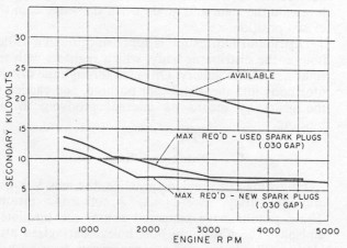
Fig. 30 - Valve timing diagram The electrical components of this engine have been designed to take advantage of a 12-volt system. Spark-plug leads have been kept short and carried well above exhaust manifold heat to make the system as efficient as possible. The distributor has been mounted on the right side of the engine to obtain an upward thrust, and consequent elimination of the thrust washer. Fig. 31 shows the considerable amount of ignition reserve available in this engine, with both new and used spark plugs. The high spark advance setting and moderate compression ratio are both big factors in obtaining this reserve. It is our experience that this relationship of voltage available to voltage required definitely improves cold starting, and helps reduce the ill effects of spark-plug-gap increases and deposits.
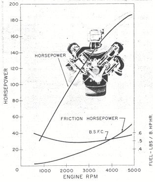
Fig. 31 - Ignition reserve Performance Fig. 32 shows the full-throttle gross performance curves of the new American Motors' engine. These curves are based on dynamometer results obtained with best-power fuel and spark advance, an 8.0:1 compression ratio, and corrected to standard SAE conditions.
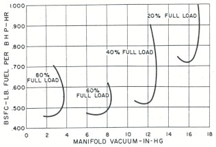
Fig. 32 - Full-throttle performance As can be noted in Fig. 32 (above), the peak horsepower of 190 is obtained at an engine speed of 4900 rpm. The friction horsepower curve shows the results of the relatively short stroke design and weight reduction in moving parts, in that it reaches a value of only 34 hp at 4000 rpm. The specific fuel consumption curve contains the results of attention to the economy factor. It shows a low rate over the entire speed range, and a minimum value of 0.485 LB of fuel per bhp-hr. The fuel fishhooks plotted in Fig. 33 give the carburetor flow requirements of part-throttle operation at 2400 rpm.
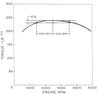
Fig. 33 - Part-throttle fuel requirements at 2400-RPM The torque curve shown in Fig. 34 depicts one of the most significant features of this engine. Torque is actually one of the more important indications of an engine's ability to give outstanding output, and it also gives the best picture of an engine's real performance in a car. It can be seen that this power-plant has a relatively flat torque curve, and actually shows a differential from peak of only 4% in the engine speed range of 1500-3500 rpm. The maximum torque of 240 LB/ft is obtained at 2500 rpm.
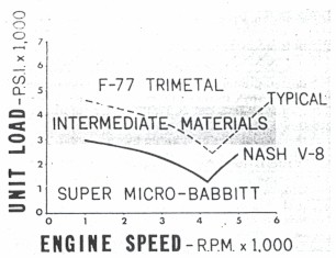
Fig. 34 - Torque curve for full-throttle performance Conclusion As has been stated earlier in this paper, we had some very definite objectives in mind when we initiated our engine program. Some of these objectives were peculiar to our plans at American Motors, while others were more common with aims found throughout the automotive industry. In short, our objective was an engine with maximum flexibility with regard to future displacement requirements without sacrificing any of the performance features of the power-plant. Economy of operation and manufacturing processes, along with excellent weight and durability characteristics, were all part of our aims. We think that we have succeeded in reaching these objectives, and have produced an engine that is second to none. It is an engine of which we are justly proud. Acknowledgment The entire program was under the direction of Meade F. Moore, Vice-President of Automotive Research and Engineering, and through his efforts the project was carried on cooperatively by our Kenosha and Detroit Engineering Departments. Obviously, such a division of both design and development required the utmost in teamwork by F. F. Kishline, Chief Engineer, and his assistants, E. L. Monson and J. S. Voigt in Kenosha, and by R. H. Isbrandt, Chief Design Engineer, and W. S. Berry, Chief Mechanical Engineer, in Detroit. D I S C U S S I O N Discusses Valve-Gear Problems Of the New V-8 Engine -Vincent Ayres Eaton Mfg. Co. The new American Motors V-8 engine represents a noteworthy achievement in producing a design to meet satisfactorily a set of specifications. Manufacture of both L-head and overhead-valve engines for many years acquainted their engineers with the operating differences between the two types of valve gear. Therefore, it is not surprising that in this paper they have discussed the recognized need for valve-train lightness and rigidity which is so necessary for good high-speed performance. The use of hydraulic valve lifters and the knowledge that the valve train will operate satisfactorily without pump-up or other disagreeable effects at speeds in excess of 5000 rpm, is a tribute to their design ability. Good high-speed motion can be obtained in an L-head valve gear with high-lift cams having sharp changes in acceleration, due to the inherent rigidity of the parts. We have photographed velocity and acceleration oscilloscope diagrams at high speed that appear to be almost theoretical. However, an overhead valve train may have five to ten times the amount of deflection and this lowered valve-gear frequency may permit severe vibrations to occur in the operating speed range. The amplitude of these vibrations is greater with a cam, which abruptly moves the valve train, than when the contour is designed to produce smooth motion. Gradual changes in acceleration or rate of loading are most desirable for a cam in overhead-valve systems. Hydraulic lifters cannot be used in a valve train that will not behave at high speeds. The cam contours used in the American Motors V-8 engine were developed to produce gradual changes of acceleration in order to minimize the high-speed valve-train vibration. The vibration which does occur, is of low amplitude, which is within the tolerance of the hydraulic lifter. The material selected for both the camshaft and tappet, known to the industry as hardenable cast iron, will prove to be a worthwhile choice. This is the combination in most widespread use, and has the ability to resist wear, scuffing and spalling under varied types of service with the variety of lubricating oils currently on the market. The Parco-Lubrite tappet face coating and the controlled cam surface finish meet with recognized standards for satisfactory break-in. The problem of adequate valve-stem lubrication without excessive oil consumption or valve-stem scuffing was solved by American Motors engineers on engines formerly produced. This knowledge assisted them in arriving at a satisfactory combination for their new V-8 engine. It is my understanding that they will continue to use valve stems with a "characterized" surface which is produced by controlled grinding, which results in a surface finish of approximately 40 micro-in. This provides needed oil-carrying capacity under conditions of borderline lubrication that would result in scuffing or valve squawk if both valve stem and guide were smooth. The intake valve material of Silchrome No. 1 and the 2112N material for the exhaust-valve head have adequate strength and corrosion resistance properties to meet passenger-car service requirements. Designing Bearings for the New Engine -Edwin Crankshaw Cleveland Graphite Bronze Co. Since our association with this engine development is from the bearing standpoint I would like to apply my comments to those things which affect bearing performance. Early in the development stages of this engine Mr. Adamson requested that we assist him in investigating the bearing design aspects. An early look at the bearing requirements of this engine allowed the flexibility of choosing bearing sizes to not only suffice for this particular engine but also to permit engine power growth facing a major bearing dimensional change. This close collaboration resulted in a thorough evaluation of bearing requirements, much of which was based on calculations as to the bearing loads, developed bearing oil film thickness, bearing operating temperatures, and oil flow requirements. The set of bearing sizes and design which was finally agreed upon were woven into the design of this engine, and it is quite apparent that American Motors has an engine that is sufficiently flexible to be readily adapted to future displacement requirements, higher compression ratios, and any of the other forward-reaching design advancements of the automotive industry today. It is also apparent that the crankshaft forging is designed to give 100% balance for much heavier reciprocating and rotating weights than are now carried, and that the water and oil pumps have a greater capacity than presently required. We have also noted with equal interest that the main bearing caps and bolts, as well as the connecting rods, have likewise been designed for greater load-carrying capacity and more successful bearing performance. In Fig. A you can see that the bearing loads for the entire speed range are well within the capacity of the microbabbitt bearing to perform satisfactorily. As bearing loads increase in the future, it will be quite possible to utilize other bearing materials, namely, the intermediate duty type. And then, if loads should climb still higher, they can be easily accommodated on the trimetal-type bearing which, of course, is the highest duty bearing on the market today.
Fig. A - Maximum rod bearing loads |
 and use it to buy the FSJ decal.